Chemical and Process Engineering Resources
Cooling Towers: Design and Operation Considerations
Nov 08 2010 12:50 PM | Chris Haslego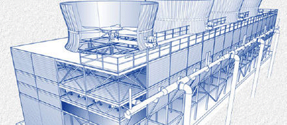
Cooling towers are a very important part of many chemical plants. They represent a relatively inexpensive and dependable means of removing low grade heat from cooling water.
The make-up water source is used to replenish water lost to evaporation. Hot water from heat exchangers is sent to the cooling tower. The water exits the cooling tower and is sent back to the exchangers or to other units for further cooling.
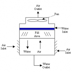
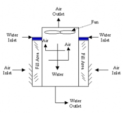
Cooling towers fall into two main sub-divisions: natural draft and mechanical draft. Natural draft designs use very large concrete chimneys to introduce air through the media. Due to the tremendous size of these towers (500 ft high and 400 ft in diameter at the base) they are generally used for water flowrates above 200,000 gal/min. Usually these types of towers are only used by utility power stations in the United States. Mechanical draft cooling towers are much more widely used. These towers utilize large fans to force air through circulated water. The water falls downward over fill surfaces which help increase the contact time between the water and the air. This helps maximize heat transfer between the two.
Mechanical draft towers offer control of cooling rates in their fan diameter and speed of operation. These towers often contain several areas (each with their own fan) called cells.
This movement of heat can be modeled with a relation known as the Merkel Equation:
where:
KaV/L = tower characteristic
K = mass transfer coefficient (lb water/h ft2)
a= contact area/tower volume
V = active cooling volume/plan area
L = water rate (lb/h ft2)
T1 = hot water temperature (°F or °C)
T2 = cold water temperature (°F or °C)
T = bulk water temperature (°F or °C)
hw = enthalpy of air-water vapor mixture at bulk water temperature (J/kg dry air or Btu/lb dry air)
ha = enthalpy of air-water vapor mixture at wet bulb temperature (J/kg dry air or Btu/lb dry air)
Thermodynamics also dictate that the heat removed from the water must be equal to the heat absorbed by the surrounding air:
where:
L/G = liquid to gas mass flow ratio (lb/lb or kg/kg)
T1 = hot water temperature (0F or 0C)
T2 = cold water temperature (0F or 0C)
h2 = enthalpy of air-water vapor mixture at exhaust wet-bulb temperature (same units as above)
h1 = enthalpy of air-water vapor mixture at inlet wet-bulb temperature (same units as above)
where:
Δh1 = value of hw-ha at T2+0.1(T1-T2)
Δh2 = value of hw-ha at T2+0.4(T1-T2)
Δh3 = value of hw-ha at T1-0.4(T1-T2)
Δh4 = value of hw-ha at T1-0.1(T1-T2)
Figure 5 below shows a graphical representation of how heat is tranferred between the warm water and cooler surrounding air:
The following represents a key to Figure 5:
C' = Entering air enthalpy at wet-bulb temperature, Twb
BC = Initial enthalpy driving force
CD = Air operating line with slope L/G
DEF = Projecting the exiting air point onto the water operating line and then onto the temperature axis shows the outlet air web-bulb temperature
As shown by Equation 1, by finding the area between ABCD in Figure 5, one can find the tower characteristic. An increase in heat load would have the following effects on the diagram in Figure 5:
The area ABCD is expected to change with a change in L/G, this is very key in the design of cooling towers.
The make-up water source is used to replenish water lost to evaporation. Hot water from heat exchangers is sent to the cooling tower. The water exits the cooling tower and is sent back to the exchangers or to other units for further cooling.
Types of Cooling Towers
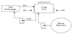 |
| Figure 1: Closed Loop Cooling Tower System |
Cooling towers fall into two main sub-divisions: natural draft and mechanical draft. Natural draft designs use very large concrete chimneys to introduce air through the media. Due to the tremendous size of these towers (500 ft high and 400 ft in diameter at the base) they are generally used for water flowrates above 200,000 gal/min. Usually these types of towers are only used by utility power stations in the United States. Mechanical draft cooling towers are much more widely used. These towers utilize large fans to force air through circulated water. The water falls downward over fill surfaces which help increase the contact time between the water and the air. This helps maximize heat transfer between the two.
Mechanical Draft Towers
Mechanical draft towers offer control of cooling rates in their fan diameter and speed of operation. These towers often contain several areas (each with their own fan) called cells.
Cooling Tower Theory
Heat is transferred from water drops to the surrounding air by the transfer of sensible and latent heat.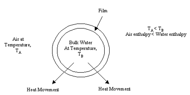 |
| Figure 4: Water Drop with Interfacial Film |
This movement of heat can be modeled with a relation known as the Merkel Equation:
 | Eq. (1) |
where:
KaV/L = tower characteristic
K = mass transfer coefficient (lb water/h ft2)
a= contact area/tower volume
V = active cooling volume/plan area
L = water rate (lb/h ft2)
T1 = hot water temperature (°F or °C)
T2 = cold water temperature (°F or °C)
T = bulk water temperature (°F or °C)
hw = enthalpy of air-water vapor mixture at bulk water temperature (J/kg dry air or Btu/lb dry air)
ha = enthalpy of air-water vapor mixture at wet bulb temperature (J/kg dry air or Btu/lb dry air)
Thermodynamics also dictate that the heat removed from the water must be equal to the heat absorbed by the surrounding air:
 | Eq. (2) |
 | Eq. (3) |
where:
L/G = liquid to gas mass flow ratio (lb/lb or kg/kg)
T1 = hot water temperature (0F or 0C)
T2 = cold water temperature (0F or 0C)
h2 = enthalpy of air-water vapor mixture at exhaust wet-bulb temperature (same units as above)
h1 = enthalpy of air-water vapor mixture at inlet wet-bulb temperature (same units as above)
The tower characteristic value can be calculated by solving Equation 1 with the Chebyshev numberical method:
 | Eq. (4) |
where:
Δh1 = value of hw-ha at T2+0.1(T1-T2)
Δh2 = value of hw-ha at T2+0.4(T1-T2)
Δh3 = value of hw-ha at T1-0.4(T1-T2)
Δh4 = value of hw-ha at T1-0.1(T1-T2)
Figure 5 below shows a graphical representation of how heat is tranferred between the warm water and cooler surrounding air:
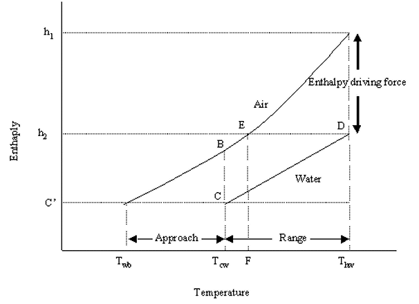 |
| Figure 5: Graphical Representation of the Tower Characteristic |
The following represents a key to Figure 5:
C' = Entering air enthalpy at wet-bulb temperature, Twb
BC = Initial enthalpy driving force
CD = Air operating line with slope L/G
DEF = Projecting the exiting air point onto the water operating line and then onto the temperature axis shows the outlet air web-bulb temperature
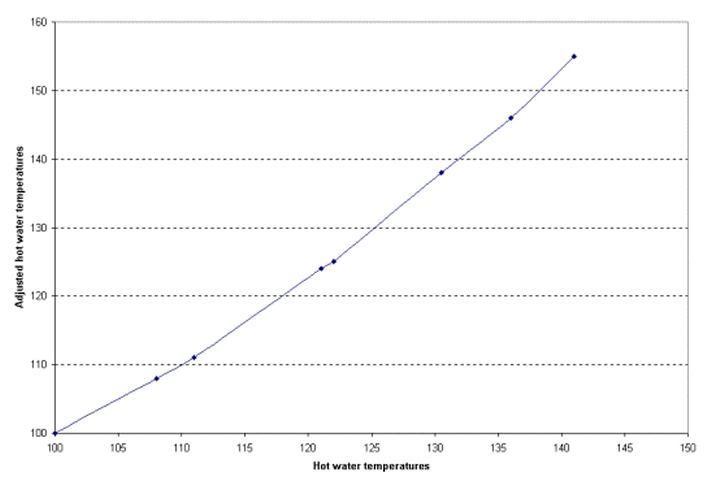 |
| Figure 6: Adjusted Hot Water Temperature |
As shown by Equation 1, by finding the area between ABCD in Figure 5, one can find the tower characteristic. An increase in heat load would have the following effects on the diagram in Figure 5:
- Increase in the length of line CD, and a CD line shift to the right
- Increases in hot and cold water temperatures
- Increases in range and approach areas
The area ABCD is expected to change with a change in L/G, this is very key in the design of cooling towers.

 FB
FB

3 Comments
Thank you for your valuable presentation.