Jump to content


Photo * * * * * 1 votes

Deoiling Hydrocyclones And Their Performance Prediction


Deoiling Hydrocyclones And Their Performance Prediction Dear All,

Today's blog entry relates to liquid-liquid hydrocyclones used in produced water treatment in the oil & gas industry.

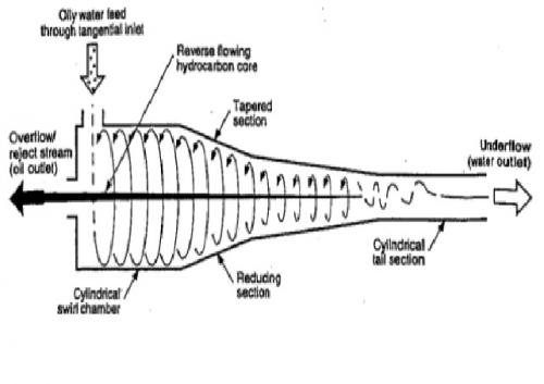
The static hydrocyclone has rapidly been accepted as a compact and efficient means of removing dispersed hydrocarbons from water. The basic design of the static hydrocyclone is illustrated schematically in the figure below:
Attached Image

The water containing the dispersed hydrocarbons enters the hydrocyclone through a tangential inlet atthe top of the swirl chamber. As the liquids swirl along the hydrocyclone, the centrifugal forces genarated promote the separation of the hydrocarbon and water phases, with the hydrocarbon phase forming a thin core at the centre of the hydrocyclone.

By maintaining a suitable pressure ratio between the clean water outlet stream and the reject oil outlet stream, the geometry of the hydrocyclone will result in the thin hydrocarbon core flowing in a reverse direction, exiting from the top of the swirl chamber. The clean water exits from the tail section of the hydrocyclone.

The following definitions are commonly used for hydrocyclones:
Feed: The oil water stream entering the hydrocyclone
Underflow: The clean water stream exiting from the tail of the hydrocyclone
Reject Stream or Overflow: The concentrated hydrocarbon stream exiting from the head of the hydrocyclone through the reject port
Reject Ratio ®: The ratio of the reject and feed stream volumetric flow rates (R = Qreject / Qfeed)

Performance Prediction:
Cut Size Diameter:
The cut size diameter is a droplet diameter which can be used to characterize the separation performance of a hydrocyclone.

A common cut size diameter definition is the 50% cut size d50.This is defined as the hydrocarbon droplet diameter which has a 50% probability of leaving the hydrocyclone in the reject stream and a 50% probability of leaving the hydrocyclone in the water outlet stream i.e.if

nd, reject / nd,out = 1 then d = d50

Another commonly used cut size is d75, representing the hydrocarbon droplet size with a 75% chance of being removed from the water stream.

Cut Size Diameter Correlations:
Several correlations are available for the prediction of the droplet cut size. The following correlations are presented:

Bradley Equation:

d50 = 0.053*Dcycl*(ρc / (Rei*Δρ))^0.5

where:
d50 = droplet size diameter as defined above, m
Dcycl = Diameter of the cylindrical hydrocyclone chamber, m
ρc = Density of the continuous phase (water), kg/m3
Δρ = Density diff. between the continuous phase (water) (ρc) and the dispersed phase (oil) (ρoil), kg/m3
Note: The min. recommended density difference for a hydrocyclone is 50 kg/m3 @operating temperature


Rei = Di*Vi*ρc / μc

where:
Rei = Reynolds number at the hydrocyclone inlet, dimensionless
Di = inlet diameter at hydrocyclone inlet, m
Vi = Fluid velocity at inlet, m/s
μc = viscosity of the continuous phase (water), kg/m-s

Rietema Equation:

d50 = 0.51*Dcycl*[ρc / ((Rei)^1.375*Δρ)]^0.5

where:
d50 = droplet size diameter as defined above, m
Dcycl = Diameter of the cylindrical hydrocyclone chamber, m
ρc = Density of the continuous phase (water), kg/m3
Δρ = Density diff. between the continuous phase (water) (ρc) and the dispersed phase (oil) (ρoil), kg/m3
Note: The min. recommended density difference for a hydrocyclone is 50 kg/m3 @operating temperature


Rei = Di*Vi*ρc / μc

where:
Rei = Reynolds number at the hydrocyclone inlet, dimensionless
Di = inlet diameter at hydrocyclone inlet, m
Vi = Fluid velocity at inlet, m/s
μc = viscosity of the continuous phase (water), kg/m-s

Coleman-Thew Empirical Model:

d75 = (Hy75*Dcycl ^3*μc / (Q*Δρ))^0.5
where:
d75 = droplet size diameter as defined above, m

Dcycl = Diameter of the cylindrical hydrocyclone chamber, m
ρc = Density of the continuous phase (water), kg/m3

μc = viscosity of the continuous phase (water), kg/m-s
Q = Volumetric flow rate at inlet of hydrocyclone, m3/h
Δρ = Density diff. between the continuous phase (water) (ρc) and the dispersed phase (oil) (ρoil), kg/m3
Note: The min. recommended density difference for a hydrocyclone is 50 kg/m3 @operating temperature


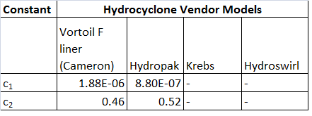
Hy75 = c1*(ReD)^c2
where:
ReD = 4*Q*ρc / (π*Dcycl*μc)
Hy75 = hydrocyclone number, dimensionless
ReD = Hydrocyclone reynolds number, dimensionless

ρc = Density of the continuous phase (water), kg/m3
c1 & c2 = Empirically derived constants based on the hydrocyclone model

Some constants are tabulated below for some vendor models
Attached Image

This is all for today. Questions and comments from the members of "Cheresources" are welcome.

Regards,
Ankur.


Dear Ankur,


I am working in a crude oil treatment plant and i am assigned a project for choosing a reliable process for the treatment of the produced water which should reinjected back to well.  The treated water should have less than 10ppm oil and 30ppm solid particles. This process must have proved it's efficiency in other partsof the world.


Regards,

L.Benabed

Benabed,


The following is a well established process to treat produced water so that it can be reinjected to wells post-treatment


The sequence is described below:


Send the produced water to Skim tank to remove bulk oil. The inlet oil quantity in skim tank could be from 3000 to 5000 ppm.


The outlet water from a well designed skim tank will contain a maximum of 200 ppm of oil.


The outlet water from the skim tank will be sent to a Dissolved Gas Flotation (DGF) unit. A well designed DGF can bring down the oil content to 20 ppm or less in the effluent coming out of the DGF.


Since your requirement is of 10 ppm or less you will need a polishing step to bring it down to 10 ppm or less. A standard polishing equipment is a "Nutsche" filter which will ensure the desired properties of the water for well injection.


You may also require some disinfection of the water using chemical treatment such as chlorination or sodium hypochlorite dosing after the polishing step to control sulphate reducing bacteria which can cause corrosion. These are standard skid mounted chemical dosing packages available from vendors.


The sequence described above gives an overview of standard treatment of produced water followed globally.


Hope this helps.


Regards,

Ankur,

Dear Ankur,


Thank you for your reply.What about the removal of solid particles especialy mud which is causing problems in  existing treatment facilities like degazing and DGFdrum. Can you send me the design procedure of the skimming tank and how it looks like.


Regards,

L.Benabed

Hello Mr Ankur,

Can I get the reference list for this equation?

Thank you very much

Hello Mr Ankur,

Can I get the reference list for this equation?

Thank you very much

Esrada,


If you google with the name of the equation, you will get the reference of the papers with the author. I had referenced it from a document called "Shell De-oiling Manual".


Regards,

Ankur.

Dear Ankur,


Thank you for your reply.What about the removal of solid particles especialy mud which is causing problems in  existing treatment facilities like degazing and DGFdrum. Can you send me the design procedure of the skimming tank and how it looks like.


Regards,

L.Benabed

Benabed,


Refer the link below and the equations 4,5 and 6 for sizing skim vessels:


http://petrowiki.org...bons_from_water


Details as well as the schematic for skim vessrls are also given in the book "Surface Production Operations by K. Arnold and M. Stewart. The equations mentioned in the link above are also given in this book from page 514 onwards which give the detailed methodology of sizing skim vessels.


Hope this helps.


Regards,

Ankur.


Hello Mr Ankur,

Can I get the reference list for this equation?

Thank you very much

Esrada,


If you google with the name of the equation, you will get the reference of the papers with the author. I had referenced it from a document called "Shell De-oiling Manual".


Regards,

Ankur.


Thank you very much

Dear Ankur,


Let's say we have solid-liquid density difference in the equation. Can we substitute it with the density difference between oil and water?


Regards,

Esrada

Dear Ankur,


Let's say we have solid-liquid density difference in the equation. Can we substitute it with the density difference between oil and water?


Regards,

Esrada

Esrada,


Your question is not clear to me. Please give some more explanation.


Regards,

Ankur.


Dear Ankur,


Let's say we have solid-liquid density difference in the equation. Can we substitute it with the density difference between oil and water?


Regards,

Esrada

Esrada,


Your question is not clear to me. Please give some more explanation.


Regards,

Ankur.


Dear Ankur,
For example, 
 
we have an equation like this
d50^2=K[(D^1.4/Q^0.55)(u^0.58/(ps-pl)^0.5)
where ps is the density of solid
and pl is density of liquid
 
This equation is used to predict the cut size of particles in solid-liquid hydrocyclone.
Can we use it for liquid-liquid hydrocyclone instead?

Esrada,


I have not come across the equation you have mentioned. Most of these equations are empirical in nature and I would not substitute one parameter (solid density) with another parameter (liquid density) if I was in your place.


Regards,

Ankur.

Hi Ankur,
 
I need to design an hydrocyclone for degassing a low-pressure water/oxygen stream, leaving an electrolytic cell. I have found several calculation methods for different applications, but these, as you say, are empirical, and I don't dare to change a single parameter in them. I know the Muschelknautz method could be applied (with some additional considerations) for ''demisting'' hydrocyclones, but in my case, it's an entirely different application. Nevertheless, I have seen some good articles (and patents) and have a good idea of some design features the hydrocylone may have. Still, I lack information concerning the hydrocyclone design/sizing. I intend to take a ''standard geometry'' (perhaps Rietema or Bradley) and work around it, but do you know of a modelling method or any source of information it could serve my endeavour? Thanks.

Latest Visitors

  • Photo
    DB Shah
    Yesterday, 10:58 PM
  • Photo
    wolf_0605
    Yesterday, 06:24 PM
  • Photo
    Azam2
    Yesterday, 03:49 PM
  • Photo
    Brocklesnar
    Yesterday, 04:45 AM
  • Photo
    Jayaramchem
    Yesterday, 03:01 AM
  • Photo
    rukkeshjr
    Yesterday, 02:58 AM
  • Photo
    khaigreen
    Yesterday, 01:18 AM
  • Photo
    marioaochoa
    06 Nov 2024 - 11:16
  • Photo
    Fort
    06 Nov 2024 - 04:58