Jump to content


Featured Articles

Check out the latest featured articles.

File Library

Check out the latest downloads available in the File Library.

New Article

Product Viscosity vs. Shear

Featured File

Vertical Tank Selection

New Blog Entry

Low Flow in Pipes- posted in Ankur's blog

Overflow Pipe Sizing


This topic has been archived. This means that you cannot reply to this topic.
13 replies to this topic
Share this topic:
| More

#1 surigaonon

surigaonon

    Junior Member

  • Members
  • 10 posts

Posted 13 June 2013 - 12:24 AM

I would like to ask your help on what formula i'm going to use in determining the overflow pipe size. I'm not really sure whether i will use the ( square root of rho*g*h ) as the formula in calculating the velocity and flow rate. Or do i need to use the weir formula. Thank you very much.


please refer to the sketch below...


6dffd509-5c7b-4154-96c5-ad3df8deaad4.jpg


#2 breizh

breizh

    Gold Member

  • Admin
  • 6,715 posts

Posted 13 June 2013 - 12:50 AM

Consider the search engine in this Forum & gravity flow .

Hope this helps

Breizh


#3 fallah

fallah

    Gold Member

  • ChE Plus Subscriber
  • 5,019 posts

Posted 13 June 2013 - 02:21 AM

Hi,


API 650 tanks don't normally have overflow connections. There is no unique rule to size the oveflow line for the tanks, just you should size such that there wouldn't be created so back pressure during overflow to overpressurize the tank more than its MAWP.


#4 mansari

mansari

    Veteran Member

  • Store Customers
  • 46 posts

Posted 13 June 2013 - 02:27 AM

Inlet flow is your starting point to size the overflow outlet. For example, you have a maximum inlet flow of 100 gpm through 2" line at a velocity of 10 ft/s. Now you have to remove this water from the basin so that level should not rise in it. A good assumption for velocity in gravity pipes is 1 ft/s. Therefore calculate pipe size for 100 gpm and 1 ft/s using V = gpm /(2.448 x d^2) which comes out to be 6.4 inches. Therefore a 6" sch 5S with an ID of 6.4 would be adequate


#5 katmar

katmar

    Gold Member

  • ChE Plus Subscriber
  • 687 posts

Posted 13 June 2013 - 05:26 AM

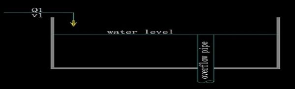
The way you have drawn your overflow pipe is what I would call a "vertical standpipe" or a "tundish".  It is a common way to control the level in a tank.  There are a few aspects to consider in designing them, but probably using Mansari's recommendation of 1 ft/s will get you to a workable design very quickly.


The first thing to realise is that the standpipe will not run full (unless you are controlling the flow externally).  If it were to run full then you would need the entrance to be flooded.  However, running it this way means that for the overflow rate to vary in order to be able to accommodate any variations in inflow will require the tank level to vary - and this is what you do NOT want.


So this means that you will run the standpipe in part-full mode - and it must therefore be self venting.  It also means that the entrance will not be flooded and as you suspected the entrance has to be considered as a circular weir.  Sometimes the top of the standpipe is made like a funnel or conical reducer to increase the circumference of the weir.


#6 surigaonon

surigaonon

    Junior Member

  • Members
  • 10 posts

Posted 13 June 2013 - 09:05 AM

thank you very much for the replies.


@Mansari / Katmar, sir does this means i can use the Q=AV formula for this calculation. I always thought that this formula can be applied only on pressure flow and for gravity flow  the root of 2*g*h will be used or the manning formula.


Edited by surigaonon, 13 June 2013 - 09:18 AM.


#7 mansari

mansari

    Veteran Member

  • Store Customers
  • 46 posts

Posted 13 June 2013 - 09:45 AM

Volumetric flow rate is always flow area times velocity, regardless of operating pressure. It is the velocity value, taken for sizing of the line. For example, normal pressurized liquid flow, we can take a velocity of 5-7 ft/s, for pump suction, this value reduces to < 3 ft/s to minimize flow resistance. Likewise, for gravity driven flow, 1 ft/s could be a good assumption


#8 katmar

katmar

    Gold Member

  • ChE Plus Subscriber
  • 687 posts

Posted 13 June 2013 - 10:36 AM

In the case of a vertical downflow drain where the liquid does not fill the cross section of the pipe the velocity calculated by V = Q/A is called the "superficial velocity".  It can be argued that this velocity has no basis in reality because the true flow area is less than the cross sectional area of the pipe, but it turns out to be a very useful concept in two phase flow.


#9 surigaonon

surigaonon

    Junior Member

  • Members
  • 10 posts

Posted 14 June 2013 - 08:59 AM

i'm really grateful for the answers you had given me. it really helps me a lot and gave me additional knowledge. Thank you once again for sharing your ideas/knowledge. More power ...


#10 Padmakar Katre

Padmakar Katre

    Gold Member

  • ChE Plus Subscriber
  • 992 posts

Posted 18 June 2013 - 04:43 AM

Hi,

Design it for self venting (Liquid Froude number less than 0.3) flow.


#11 surigaonon

surigaonon

    Junior Member

  • Members
  • 10 posts

Posted 02 July 2013 - 03:05 AM

just a follow up question. in calculating the friction flow, i use the swamee jain formula in obtaining the friction factor. i usually work in metric and i'm just confused whether that formula is the same for both emperical/metric.


another one; if i have a long pipe connected from a pump and delivered to a certain place. The main pipe has branches and the main pipe size is reduced gradually until the end. (ex. 200 reduce to 100 .... 80...50 ). In calculating the friction loss for the whole delivery pipe, do i need to calculate separately based on pipe size or i can take the average pipe size .


once again i would like to thank you for the help. i'm just really have little knowledge for now with this.


#12 breizh

breizh

    Gold Member

  • Admin
  • 6,715 posts

Posted 02 July 2013 - 03:33 AM

Take a look at the equation , you should notice that f has no dimension 

f= 0.25/(log10(eps/3.7/D+5.74 /Re^0.9))^2


eps : absolute rugosity (mm) and D ( inside diameter ) (mm)  

Re :Reynolds number


For the pipe line , you should consider equivalent length of pipe ( pdf  ) and  take 80 mm as a reference for example .

hf = f (L/D) x (V^2/2g) 


hf :head loss (m) 


Hope this helps 


Breizh 


Edited by breizh, 02 July 2013 - 04:37 AM.


#13 katmar

katmar

    Gold Member

  • ChE Plus Subscriber
  • 687 posts

Posted 02 July 2013 - 05:59 AM

I agree with the method proposed by breizh - this is a tool I often use.  Just be careful in this case that if you have branches along the line that take flow from the main line you must use the correct flow rate for each section.  This will require you to calculate the overall pressure drop by summing the pressure drops for the sections, and in that case you might as well just use the actual diameters.


#14 surigaonon

surigaonon

    Junior Member

  • Members
  • 10 posts

Posted 02 July 2013 - 08:37 PM

@ Breizh , @katmar thank you very much for the replies. this really helps me a lot.


Similar Topics