 FB
FB


I am fairly newly out of school (2 years in industry) and am working on some relief valve sizing. I understand choked flow, from a theoretical standpoint, but I have a problem involving a case around a blowdown drum. If my intermittent blowdown valve is stuck fully open there is a high pressure breakthrough case on the blowdown drum (which is designed to LP steam). When calculating maximum flow through an orifice under critical/choked/sonic (whichever term you prefer) flow how can you account for the fact that it is liquid upstream of the blowdown valve and not vapor? It seems to me that a worst case scenario would be to assume the maximum amount of flash (between normal boiler pressure and LP steam relief pressure). Am I completely off base here? It seems like a fairly common case to consider when sizing blowdown systems, but I am having a hard time finding any information on it. Any information you can give would be appreciated.
Regards,
Stephen
|
|

Blowdown Valve Failure
Started by stebaldi, Mar 06 2009 12:49 PM
6 replies to this topic
Share this topic:
#2

Art Montemayor
-

- Admin
-

- 5,782 posts
Gold Member
Posted 06 March 2009 - 01:18 PM
Stephen:
Welcome to our Forums.
Sonic or choked flow is nothing out of the ordinary. It is more common place than most would imagine. For example, just about every relief device discharging a vapor flow is doing it under choked conditions. Additionally, if you have a blowdown valve that is discharging a gas or vapor it is to be expected that the results will be choked flow at the outset.
Now, with respect to your query, I don’t completely understand your statements. You state: “If my intermittent blowdown valve is stuck fully open there is a high pressure breakthrough case on the blowdown drum (which is designed to LP steam). When calculating maximum flow through an orifice under critical/choked/sonic (whichever term you prefer) flow how can you account for the fact that it is liquid upstream of the blowdown valve and not vapor?” You don’t tell us exactly WHAT it is that you are “blowing down”. Is it a vapor (steam) or a liquid? I think we both know that you can only “choke” gases or vapors (subject them to sonic flow). You certainly wouldn’t want to have liquid slugs speeding at the speed of sound. The hammer effect would be astronomical.
You further state: “It seems to me that a worst case scenario would be to assume the maximum amount of flash.” What is it that you are doing, exactly? If you are really “flashing”, then you are dealing with a liquid – probably a saturated one. Is that what is happening? If so, then we have a different case and not necessarily one of choked flow. If you supply us with complete basic data and a sketch, this will go a long way in fully appreciating your concerns and your questions. It will enable us to fully understand the problem or questions and give an intelligent answer.
This being Friday in Houston and a great weekend ahead, perhaps you can put something together for us before 4 pm.
#3
stebaldi
-
- Members
-

- 4 posts
Brand New Member
Posted 06 March 2009 - 01:53 PM
Art,
Thanks for reply. Here is a little more information:
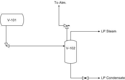
V-101 has a design pressure of 660psig and the intermittent blowdown (saturated liq at 600 psig) is sent to V-102 where LP steam (50psig) is flashed off. V-102 has a design pressure of 55psig. The problem arises if the blowdown valve is in a stuck open position, in which case you can possibly overpressure V-102 with the large amount of blowdown that would flow through a completely open valve.
The issue I am having with the choked flow is that it seems to me that you would have flashing as soon as the leading edge of the orifice is hit, which would indicate that you could get choked flow. It may not be a lot, so it may be practical to just assume it is purely liquid and back the maximum flow out from the pressure of V-102 (at relief). Obviously I haven't dealt with this before, but it seems like the amount of flashing across the valve would be minimal due to the large pressure drop in the downstream piping (~500' eq. length).
Does it seem like a good approach would be to start at the relieving pressure of V-102 (~60psig) and just back the pressure profile up to V-101 to determine the maximum flow through the valve/piping?
Thanks again,
Stephen
Thanks for reply. Here is a little more information:
V-101 has a design pressure of 660psig and the intermittent blowdown (saturated liq at 600 psig) is sent to V-102 where LP steam (50psig) is flashed off. V-102 has a design pressure of 55psig. The problem arises if the blowdown valve is in a stuck open position, in which case you can possibly overpressure V-102 with the large amount of blowdown that would flow through a completely open valve.
The issue I am having with the choked flow is that it seems to me that you would have flashing as soon as the leading edge of the orifice is hit, which would indicate that you could get choked flow. It may not be a lot, so it may be practical to just assume it is purely liquid and back the maximum flow out from the pressure of V-102 (at relief). Obviously I haven't dealt with this before, but it seems like the amount of flashing across the valve would be minimal due to the large pressure drop in the downstream piping (~500' eq. length).
Does it seem like a good approach would be to start at the relieving pressure of V-102 (~60psig) and just back the pressure profile up to V-101 to determine the maximum flow through the valve/piping?
Thanks again,
Stephen
#4
Art Montemayor
-
- Admin
-
- 5,782 posts
Gold Member
Posted 06 March 2009 - 03:20 PM
Stephen:
You don't state what is the status of the blowdown design. Is it in the proposal phase, or is it in the design or installed phase?
If the design has been done, then the PSV on V-102 has to be sized to handle the blow-through case (all the HP steam flowing in V-101). However, if V101 is only filled with a limited amount of saturated water at 600 psig, then that will be the source of the generated flash vapors (albeit, for a limited time – until the liquid drains all out).
Here, I'm assuming that V-102 is always maintained at 50 psig (whatever the overhead LP steam is connected to will ensure that V-102 is at 50 psig). Therefore, when the blowdown valve fails open, the rate of liquid being drained out will be identified by its Cv characteristics. This identifies the liquid flow going through the valve at maximum conditions. Additionally, the drained liquid is undergoing an adiabatic, free expansion that is thermodynamically identified as an isenthalpic expansion where the products are a 2-phase mixture of condensate and LP steam at 50 psig + the resulting pressure drop as it makes its way through 500 feet (!) of piping and reaches V-102. As the resulting flash steam vapor rushes through the 500 feet of piping, it is undergoing a differential pressure drop and increasing is specific volume – which, in a fixed diameter pipe, means that its speed will be increasing differentially. It is conceivable that the steam could achieve sonic velocity as it travels through the 500 feet of pipe, overcoming the frictional and configuration resistance in the system. However it would have to do it as a 2-phase mixture, and this is where it gets very "hairy" and troublesome to calculate and estimate.
The burdensome straw that is threatening to break the camel's back is the fact that the drain pipe is 500 feet in length. This is a heavy burden on any hydraulic system – much less on a 2-phase one. I would always design to have the receptacle vessel (V-102) as close to the source (V-101) and mount the drain valve directly onto a nozzle flange on V-102. This would cause the 2-phase mixture to be created as it enters V-102 and immediately be separated into two manageable phases. However, I'm guessing you don't have this choice, because that is what you would have done in the first place.
I would not assume that the amount of flashing across the valve would be minimal due to the large pressure drop in the downstream piping. We don't know the size of the downstream piping. Nor do we know the size of the 2-phase stream. I can almost sense the dire dilemma you are facing: the bigger you make the downstream piping, the more atrocious the piping capital cost. Your enemy is the distance involved between both vessels.
By a simple heat and mass balance, we know that:
where,
F = the liquid flow into the blowdown valve (identified by its Cv value);
L = the resultant saturated liquid produced downstream at the downstream pressure;
hL = enthalpy of the resultant liquid due to the flash;
Hv = enthalpy of the resultant vapor due to the flash;
hF = enthalpy of the high pressure saturated water being flashed.
Since you know the enthalpies, you can calculate for the resultant LP saturated water produced and the saturated vapor formed. If you find that there is a need to do detailed calculations, you can set up a dynamic model on a simulator and calculate the differentially formed vapor rate and see if it actually chokes. If it does, then you know you've got your maximum vapor rate.
I hope this explanation helps out.
You don't state what is the status of the blowdown design. Is it in the proposal phase, or is it in the design or installed phase?
If the design has been done, then the PSV on V-102 has to be sized to handle the blow-through case (all the HP steam flowing in V-101). However, if V101 is only filled with a limited amount of saturated water at 600 psig, then that will be the source of the generated flash vapors (albeit, for a limited time – until the liquid drains all out).
Here, I'm assuming that V-102 is always maintained at 50 psig (whatever the overhead LP steam is connected to will ensure that V-102 is at 50 psig). Therefore, when the blowdown valve fails open, the rate of liquid being drained out will be identified by its Cv characteristics. This identifies the liquid flow going through the valve at maximum conditions. Additionally, the drained liquid is undergoing an adiabatic, free expansion that is thermodynamically identified as an isenthalpic expansion where the products are a 2-phase mixture of condensate and LP steam at 50 psig + the resulting pressure drop as it makes its way through 500 feet (!) of piping and reaches V-102. As the resulting flash steam vapor rushes through the 500 feet of piping, it is undergoing a differential pressure drop and increasing is specific volume – which, in a fixed diameter pipe, means that its speed will be increasing differentially. It is conceivable that the steam could achieve sonic velocity as it travels through the 500 feet of pipe, overcoming the frictional and configuration resistance in the system. However it would have to do it as a 2-phase mixture, and this is where it gets very "hairy" and troublesome to calculate and estimate.
The burdensome straw that is threatening to break the camel's back is the fact that the drain pipe is 500 feet in length. This is a heavy burden on any hydraulic system – much less on a 2-phase one. I would always design to have the receptacle vessel (V-102) as close to the source (V-101) and mount the drain valve directly onto a nozzle flange on V-102. This would cause the 2-phase mixture to be created as it enters V-102 and immediately be separated into two manageable phases. However, I'm guessing you don't have this choice, because that is what you would have done in the first place.
I would not assume that the amount of flashing across the valve would be minimal due to the large pressure drop in the downstream piping. We don't know the size of the downstream piping. Nor do we know the size of the 2-phase stream. I can almost sense the dire dilemma you are facing: the bigger you make the downstream piping, the more atrocious the piping capital cost. Your enemy is the distance involved between both vessels.
By a simple heat and mass balance, we know that:
(F/L) = (hL – Hv)/(hF – Hv)
where,
F = the liquid flow into the blowdown valve (identified by its Cv value);
L = the resultant saturated liquid produced downstream at the downstream pressure;
hL = enthalpy of the resultant liquid due to the flash;
Hv = enthalpy of the resultant vapor due to the flash;
hF = enthalpy of the high pressure saturated water being flashed.
Since you know the enthalpies, you can calculate for the resultant LP saturated water produced and the saturated vapor formed. If you find that there is a need to do detailed calculations, you can set up a dynamic model on a simulator and calculate the differentially formed vapor rate and see if it actually chokes. If it does, then you know you've got your maximum vapor rate.
I hope this explanation helps out.
#5
stebaldi
-
- Members
-
- 4 posts
Brand New Member
Posted 06 March 2009 - 04:24 PM
To clarify a little more. The boiler (V-101) has an continuous blowdown and an intermittent blowdown. The intermittent blowdown is the valve in question. It is a manually operated valve (multiple times/day I would imagine) depending on the buildup of solids/scale in the bottom of the boiler.
I think, based on API 521, if the blowdown valve fails open you have to assume that all else remains constant, which would mean the boiler feed water would continue flowing to V-101, and that flow is most likely (since I haven't calculated yet) going to be higher than the maximum flow through the blowdown valve implying that I would never run out of liquid in V-101.
The project is in the FEED phase, so line sizes are estimated right now. I can determine the differential pressure drop through the line based on the % of flash that occurs down the line. Like you said though, my major problem is determination of choked flow when it is a 2-phase mixture. I am not exactly sure how that is treated. If knowing the Cv through the valve would it be possible to just back out the flow by a pressure profile? It seems to me, and maybe it's just me, that seems to be the most straight forward way to determine what the flow through the valve would be.
As far as the length of drain line, that is a WAG using my estimation from our prelim plot plan. We have a 300' line from our furthest away blowdown source (this blowdown drum, V-102, is common to three boilers) and I may have overestimated the eq. length of fittings on a 300' line.
#6
Art Montemayor
-
- Admin
-
- 5,782 posts
Gold Member
Posted 06 March 2009 - 05:21 PM
Stephen:
If your project is at the Front End of Engineering Development (FEED), then you are free to place a conventional flow restriction device within your blow-down system that will limit the blow-down rate to a maximum, pre-determined quantity that you pre-select (& can change later, if you so wish).
You do this with a restriction orifice or nozzle. I would place it directly downstream of the blow-down valve. Should the blow-down valve fail open, this restriction would come into play and limit the flow rate on a steady-state basis.
This is analogous to what I said of the Cv on the blow-down valve. You know what will be the maximum flow rate through the valve because you should know its Cv value at the wide-open position. And as I said previously, if you know F, then you can calculate for V and L easily.
Since you are at the FEED stage, you can make a fairly accurate estimation of the correct line size and include some contingency for the line length. The final, detailed design will correct for any deviations or changes made in the design basis or layout.
#7
Qalander (Chem)
-

- ChE Plus Subscriber
-
- 829 posts
Gold Member
Posted 07 March 2009 - 09:05 AM
Fanatastic Reply Art; as usual.
This is customary that we do have RO (Restriction Orifice) employed in the piping line-up upstream of IBD (Intermittent Blow Down) systems as witnessed in almost all of the Steam Gnerating Water Tube Boilers I came across at my previous employers.
Hope this proves a little bit helpful in following the Art's advice.
Best Regards
Qalander
Similar Topics
Check Valve FailureStarted by Guest_Falah_* , 26 Mar 2025 |
|

|
||
Multiport Selector Valve (Msv)Started by Guest__1angelia23_* , 12 Mar 2025 |
|

|
||
Aspen Hysys - Blowdown Utility Heat Flux MethodStarted by Guest_yuvi.ardekar1999@gmail.com_* , 27 Feb 2025 |
|

|
||

Valve Cavity - Pressure Relief ValveStarted by Guest_CS10_* , 20 Feb 2025 |
|
|
||
Valve Cv InputsStarted by Guest_QuantumEng_* , 01 Apr 2024 |
|

|

